Atlas: reading the trackpoint with a 24-bit ADC
Replacing the Sprintek "all-in-one" TrackPoint module's PS/2 path with a bare strain-gauge stick read directly by a TI ADS1220 over SPI. Bench-proven end-to-end; PCB design is the active workstream.
Atlas’s pointing path used to run through the Sprintek “all-in-one” TrackPoint module: a strain-gauge stick with an on-board microcontroller that exposed the cursor as PS/2 over UART. It worked. It also baked decisions into someone else’s firmware: filter shape, gain curve, output rate, dead-zone. And it put a microcontroller between Atlas and its own sensor for no good reason.
So the path got shorter.
The current setup reads the strain-gauge bridge directly with a TI ADS1220, a 24-bit ΔΣ ADC over SPI, and lets Zephyr/ZMK turn that into HID cursor events. Same physical stick, same finger feel, but every link in the chain is now ours.
The old path
Sprintek "AIO" module → PS/2 packets → UART → XIAO BLE → ZMK
                       ↑
                       Sprintek MCU does ADC, filtering,
                       packet framing. Closed firmware.
The “AIO” version of the Sprintek module is convenient: four wires (V, GND, TX, RX), drop in a PS/2 driver, done. The cost is that all of the analog-to-cursor work happens inside a chip you can’t change. Want a different dead-zone? Different exponential curve? Lower output rate for power? You’re stuck.
The new path
Sprintek bare stick (4-wire strain bridge)
│
├── AIN0/AIN1: differential bridge output
├── REFP0/REFN0: ratiometric reference (IDAC1 + 2× 2400Ω divider)
▼
TI ADS1220: 24-bit ΔΣ ADC
│
▼ SPI1 (SCLK/MOSI/MISO + CS + DRDY)
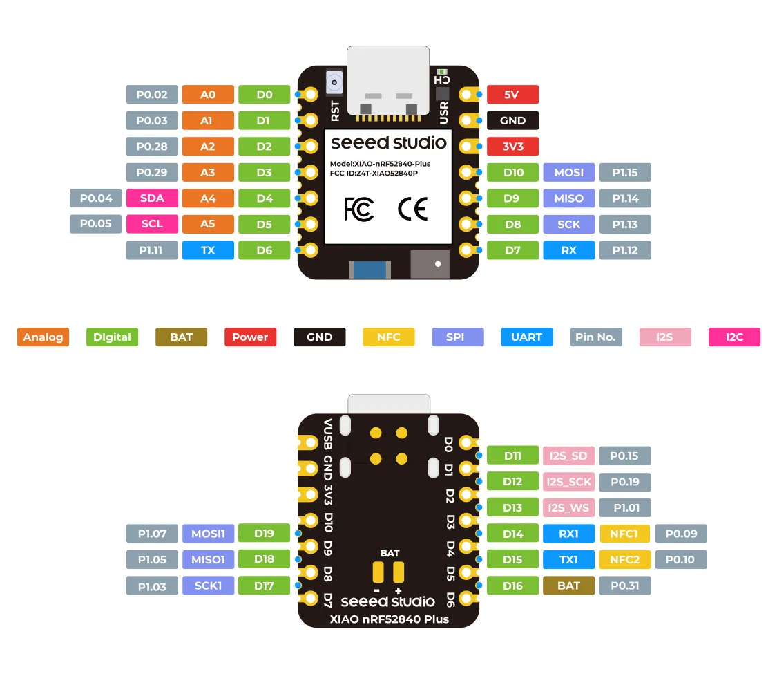
Seeed XIAO nRF52840 Plus
│
▼ Zephyr SPI driver + small state machine
HID cursor events → BLE → hostTwo design choices that mattered:
Ratiometric reference. The same IDAC current that excites the strain bridge also generates the ADC’s reference voltage across the 2400Ω resistors. Drift in the current source cancels in the ratio. What you measure is bridge imbalance, not absolute voltage. This is the trick that lets a strain gauge work at 24 bits without obsessive analog precision elsewhere.
Secondary SPI bus. The XIAO nRF52840 Plus exposes a second SPI peripheral on its side-edge tabs (SCK1/MISO1/MOSI1 on D17/D18/D19). The matrix already owns the primary SPI bus (D8/D9/D10), so the trackpoint reads happen on SPI1 with CS on D11 and DRDY on D12. Two SPI buses on one MCU: no contention, no bit-banging.
The wiring contract:
| Signal | XIAO label | nRF52840 | ADS1220 |
|---|---|---|---|
| 3V3 | 3V3 | — | AVDD + DVDD |
| GND | GND | — | AGND + DGND |
| SCLK | SCK1 (D17) | P1.03 | SCLK |
| MOSI | MOSI1 (D19) | P1.07 | DIN |
| MISO | MISO1 (D18) | P1.05 | DOUT |
| CS | I2S_SD (D11) | P0.15 | ~CS |
| DRDY | I2S_SCK (D12) | P0.19 | ~DRDY |
The I2S_SD/I2S_SCK silkscreen names refer to the alternate peripheral function on those pins; we use them as plain GPIO. The names are misleading and the schematic should not be.
Bench validation
Hand-soldered ADS1220 breakout, bare Sprintek strain-gauge stick, XIAO nRF52840 Plus, four pieces of wire-wrap. A standalone Zephyr test app at firmware/test_ads1220/ reads the ADC, turns the bridge imbalance into X/Y deltas with a basic exponential curve, and emits USB HID mouse events to a host PC.
End-to-end works. Cursor moves. Feels right.
Two things validated by the bench rig that matter for the PCB design:
- The ratiometric reference holds up. The cursor is stable at rest and tracks bridge load linearly. No drift, no temperature creep at room temperature.
- The 24-bit resolution pulls its weight. With the bridge unloaded, the noise floor sits around ±5 counts on a stationary stick; small finger pressure produces clear deltas in the hundreds. There’s headroom for a tighter dead-zone or a softer exponential than PS/2 ever gave us.
What it changes for the PCB
The PCB design now carries the ADS1220, its reference divider, decoupling, and the SPI wiring back to the controller. The keyboard matrix and the trackpoint readout share the same MCU but run on separate SPI buses, so there’s no contention.
Still pending before fab:
- Footprint check against the bare Sprintek module. The bench unit has 4 bridge tabs + 2 case-ground tabs, and the case-shield connection on the PCB needs to match that physical reality, not the AIO module’s pinout that lived in the older nets.
- IDAC1 current setting. The bench rig runs the bridge excitation conservatively; on the board it’s worth measuring SNR at a couple of current settings and picking the best one before locking the firmware default.
What it changes for the firmware
The standalone bench app proves the SPI driver works. Integrating it into ZMK proper is the remaining firmware task:
- Wrap the ADS1220 read loop as a Zephyr input device that ZMK can subscribe to.
- Drop the legacy PS/2 input source from the keymap entirely.
- Use
zmk,input-splitto forward the right half’s trackpoint events over BLE to the central, the same way key events already travel.
None of this blocks the PCB run. Once the boards arrive, the existing bench firmware drives them while the proper ZMK driver lands.
Why this was worth doing
Three reasons, in order of how much they mattered:
- Openness. Every piece of the cursor path is now something Atlas controls, from bridge excitation current to final HID curve. No closed firmware between the sensor and the keyboard.
- Feel. The default PS/2 output rate from the AIO module was fine but constrained. Reading at 24 bits over SPI lets us tune dead-zone, gain, and rate to whatever feels right, in firmware, and iterate.
- Parts simplicity. One fewer microcontroller, one fewer firmware blob, one fewer interface. The bench rig fits on a breadboard. The PCB fits a few extra passives. Nothing in the supply chain is now proprietary.
Atlas is on the feat/ads1220-integration branch on GitHub. Group buy still opening late 2026.